Thursday, 28 May 2015

Two Arduino's Communication with USART

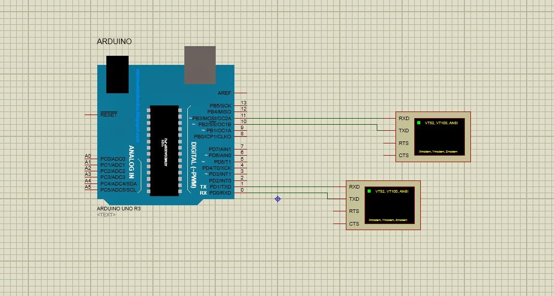
In following schematic shows the connections to establish communication between two arduino's using Hardware Usart Arduino Uno connected to the keyboard scans the human inputs using keyboard and send the keystrokes as it is to the second arduino which shows the entered data.


Code for arduino connected to the Keypad (Tx) is :
#include <Keypad.h>

const byte ROWS = 4; // Four rows
const byte COLS = 3; // Three columns
// Define the Keymap
char keys[ROWS][COLS] = {
  {
    '1','2','3'  }
  ,
  {
    '4','5','6'  }
  ,
  {
    '7','8','9'  }
  ,
  {
    '*','0','#'  }
};
// Connect keypad ROW0, ROW1, ROW2 and ROW3 to these Arduino pins.
byte rowPins[ROWS] = { 
  5,4,3,2 };
// Connect keypad COL0, COL1 and COL2 to these Arduino pins.
byte colPins[COLS] = { 
  6,7,8 }; 

// Create the Keypad
Keypad kpd = Keypad( makeKeymap(keys), rowPins, colPins, ROWS, COLS );

#define ledpin 13

void setup()
{
  Serial.begin(9600);
}

void loop()
{
  char key = kpd.getKey();
  if(key)  // Check for a valid key.
  {

    Serial.print(key);
  }

}

we need arduino Keyboard library to compile the above code, can be found http://playground.arduino.cc/code/keypad

Arduino Connected to the Virtual Terminal(Rx) is:

#define password 123
#include<SoftwareSerial.h>
SoftwareSerial mySerial(10,11);//10-Rx  11-Tx
char data_buffer[15];
boolean read_data = false;
byte index;
void setup()
{
  Serial.begin(9600);
  mySerial.begin(9600);
  mySerial.println("welcome");
  mySerial.println("please enter password with starting letter * and ending letter # like *123#");
}

void loop(){

  if(Serial.available())
  {

    char input = Serial.read();
    if (input == '*')
    {
      read_data = true;
      index = 0;
    }
    else if(input == '#')
    {
      data_buffer[index] = 0;
      read_data  = false;
      mySerial.print("the value value you entered is");
      mySerial.println(atoi(data_buffer));
      if (atoi(data_buffer) == password){
        mySerial.println("password Matched");
      }
      else{
        mySerial.println("wrong Password");
      }
    }
    else
    {
      if(read_data)
      {
        data_buffer[index] = input;
        index = index + 1;
      }
    }
  }
}//end of loop

please see the video below to see how the schematic is done


Wednesday, 27 May 2015

Proteus Virtual Terminal using Arduino Hardware and Software Serial

Proteus schematic :

Arduino Code:

#include<SoftwareSerial.h>
SoftwareSerial mySerial(10,11); // 10 - Rx    11 -Tx

void setup()
{
mySerial.begin(9600);

Serial.begin(9600);

}

void loop()
{
 Serial.println("enter  char");
 while(!Serial.available())
 {
 //wait until user enters the data
 }

 if(Serial.available())
{
 mySerial.println(Serial.read());
 }

}

Video :

Friday, 22 May 2015

Arduino Serial communication in proteus using Virtual Terminal

we can simulate the arduino serial communication using virtual terminal in the proteus

virtual terminal in proteus is located at instruments logo which highlighted as Instruments and can be located
virtual termina;
in the instruments we can choose the virtual instrument

we can select the serial transmission characteristics such as baud rate, parity... etc

virtual terminal

code which is dumped into Arduino is

const int pin = 13;
void setup()
{
pinMode(pin,OUTPUT);
Serial.begin(9600);
Serial.println("enter y to ON and n to OFF");
}

void loop()
{
while(!Serial.available())
{
//wait until user enters the data
}

if(Serial.available())
{
char input = Serial.read();
switch(input)
{
case 'y':
Serial.println("you entered y led ON");
digitalWrite(pin,HIGH);
break;
case 'n':
Serial.println("you entered n led is OFF");
digitalWrite(pin,LOW);
break;
default:
Serial.println("you entered wrong character");
}//end of switch
}//end of If

}//end of loop

Thursday, 21 May 2015

Arduino Relay driver using optocoupler in Proteus

In relay On condition
arduino_relay_ON

In relay Off condition
arduino_relay_off

Arduino Code is


const int pin =13;

void setup(){
pinMode(pin,OUTPUT);
Serial.begin(9600);
Serial.println("Please enter a char");
}

void loop(){
Serial.println("Please enter y to ON and n to OFF led");
while(!Serial.available())
{
//wait until user enters the data
}

char input;
if(Serial.available())
{
Serial.println(input = Serial.read());
if(input == 'y'){
Serial.println("you entered y led is ON");
digitalWrite(pin,HIGH);
}
else if(input == 'n'){
Serial.println("you entered n led is OFF");
digitalWrite(pin,LOW);
}
else{
Serial.println("you entered a wrong character");
}
}
}

Wednesday, 20 May 2015

Adding Arduino Library to proteus 8

when i googled to add arduino library to proteus8 version there are many examples came But I still faced the problem while installing arduino library in proteus version 8.

the usual procedure to add library is
1.download the library
2. paste it in your LIBRARY folder

the problem is I don't find the library folder in program files
so i clicked on the L in the P L device menu

library

and by clicking create library we can know the path where the LIBRARY folder is

Arduino Proteus8 turorial

simulation of arduino controlling relay.. step 1: when you double click on the Proteus8 icon the window open like this

home

step 2: go to FILE and click on NEW PROJECT a new project wizard is open like this new_project_wizard select a name and path for it and click next step 3: create the default schematic schematic click on the create schematic from the selected template and choose DEFAULT and select option for no pcb layout and and no firmware as shown in figures below pcb layoutfirmware and click finish finish after clicking finish we get a empty schematic like this empty schematic I assume that you installed Arduino Proteus library -- if not google it you can find many tutorials of how to do it. at the left panel we have some control tools to add components to the schematic control In above picture the highlighted one having names P L DEVICES when we click on P we have option to pick components pick devices IF you type Arduino in search bar you get the window like this arduino_pick select arduino UNO and click ok to add it to the devices for this we are gonna need following components 1.ULN2003 IC - relay driver 2.relay 3.dc source 4.ac source 5.lamp ULN2003 IC-- we can get this using search bar uln2003 and relay,lamp and ac source using keywords relay,lamp and alternator respectively but for dc source it took me some time to figure out what to do... we can get dc source from generator mode generator by clicking the symbol generator_sign and selecting DC dc_select and after aligning all these in the schematic get to this. arduino_relay to dump the code follow this procedure Using Arduino IDE type the following code void setup() { pinMode(13,OUTPUT); } void loop() { digitalWrite(13,HIGH); delay(1000); digitalWrite(13,LOW); delay(1000); } before verifying the code goto File -- Preferences in Arduino file menu select compilation as shown in fig preferences and press the verify button code_file copy the highlighted section and paste it in paste the above window comes by double clicking the arduino uno.. and run the simulation we can see the lamp is ON and OFF sequentially.

Tuesday, 19 May 2015

Using relay with Arduino

references :

http://www.electronics-tutorials.ws/io/io_5.html

http://www.electroschematics.com/8512/microcontroller-relay-interface-and-driver/

https://electrosome.com/interfacing-relay-8051-keil-c/