Sunday 27 December 2015

Basic Electronics - Lec3 Diodes

The key function of an diode is to control the direction of current-flow. Current passing through a diode can only go in one direction, called the forward direction. Current trying to flow the reverse direction is blocked. They’re like the one-way valve of electronics.
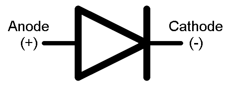
The terminal entering the flat edge of the triangle represents the anode. Current flows in the direction that the triangle/arrow is pointing, but it can’t go the other way.

Forward Voltage
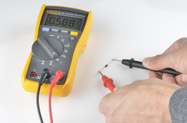
In order to “turn on” and conduct current in the forward direction, a diode requires a certain amount of positive voltage to be applied across it. The typical voltage required to turn the diode on is called the forward voltage (VF). It might also be called either the cut-in voltage or on-voltage.

it is Typically 0.5 volts for Silicon Diode.
BreakDown Voltage :

Breakdown Voltage

If a large enough negative voltage is applied to the diode, it will give in and allow current to flow in the reverse direction. This large negative voltage is called the breakdown voltage. Some diodes are actually designed to operate in the breakdown region, but for most normal diodes it’s not very healthy for them to be subjected to large negative voltages.


Working With LED's :
LED - Light Emitting Diode
The LED does have and "equivalent" resistance, but it's value is wholly dependent on the value of the current flowing through the LED and dynamically changes with it.
To deal with an LED you start with the forward current that you need, typically about half it's maximum rated value (lets use 20 mA).  
Next you estimate what the forward voltage drop will be with that current flowing through the LED.  If you have a datasheet for the LED you may be able to get a fairly accurate value, otherwise you take a guess based upon your experience or the experience of others (I usually use 1.7v for a red LED).  
Next you pick out a supply voltage which must be higher than the voltage you just determined (I'll use 5v).  
Now you can use Ohm's law to determine the required resistance.  The voltage across the resistor will be the difference between the supply voltage you decided to use and the voltage that you guessed would be across the LED (5v - 1.7v = 3.3v).  The current through the resistor will be the same as the current through the LED (20mA).   Ohm's law for the resistor says that R = V/I (R = 3.3/0.020 = 165 ohms).  
You then pick the closest value resistor that you happen to have and stick that in your circuit.  Most likely the current won't be exactly what you desired and the LED voltage won't be what you guessed would be there but you won't see any smoke either and you will see light from the LED.
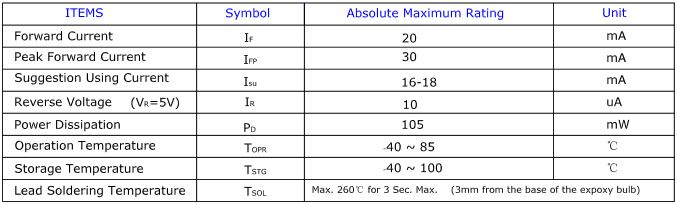
Check the Data Sheet of Sample LED here.

And see the Maximum Values

Basic Electronics - Les 3 More About Semiconductors

P type and N type Semi Conductors
we can Divide the materials into Three Types According to its Conducting Nature
1. Conductor
2. Insulators
3. Semi Conductors

Insulators : These are having More resistance. have poor Conductivity ex: Rubber

Conductors : Having More Free Electrons than Insulators hence can having High Conductance ex: Copper

Semiconductors: these are having the conductivity range Between the Conductors and Insulators ex: Silicon and Germanium.. with materials they developed all these mysterious Chips.

But the Thing is we cannot use Semiconductors Directly (pure ones i.e intrinsic form), we must able to change number of holes or electrons to change their proper for our cause.

so we are gonna add some known impurities to them so we can alter their properties.

The process of purposefully adding impurities to materials is called doping; semiconductors with impurities are referred to as "doped semiconductors".

ah.. Doping Its just a Fancy Word,,

 p-type and n-type materials are simply semiconductors, such as silicon (Si) or germanium (Ge), with atomic impurities; the type of impurity present determines the type of the semiconductor. 

P-type

In a pure (intrinsic) Si or Ge semiconductor, each nucleus uses its four valence electrons to form four covalent bonds with its neighbors (see figure below). Each ionic core, consisting of the nucleus and non-valent electrons, has a net charge of +4, and is surrounded by 4 valence electrons. Since there are no excess electrons or holes In this case, the number of electrons and holes present at any given time will always be equal.
                                                    An intrinsic semiconductor. Note each +4 ion is surrounded by four electrons


Now, if one of the atoms in the semiconductor lattice is replaced by an element with three valence electrons, such as a Group 3 element like Boron (B) or Gallium (Ga), the electron-hole balance will be changed. This impurity will only be able to contribute three valence electrons to the lattice, therefore leaving one excess hole (see figure below). Since holes will "accept" free electrons, a Group 3 impurity is also called an acceptor.
                                                       A semiconductor doped with an acceptor. An excess hole is now present
Because an acceptor donates excess holes, which are considered to be positively charged, a semiconductor that has been doped with an acceptor is called a p-type semiconductor; "p" stands for positive. Notice that the material as a whole remains electrically neutral. In a p-type semiconductor, current is largely carried by the holes, which outnumber the free electrons. In this case, the holes are the majority carriers, while the electrons are the minority carriers.

N-type

In addition to replacing one of the lattice atoms with a Group 3 atom, we can also replace it by an atom with five valence electrons, such as the Group 5 atoms arsenic (As) or phosphorus (P). In this case, the impurity adds five valence electrons to the lattice where it can only hold four. This means that there is now one excess electron in the lattice (see figure below). Because it donates an electron, a Group 5 impurity is called a donor. Note that the material remains electrically neutral.
                                                        A semiconductor doped with a donor. A free electron is now present.

Donor impurities donate negatively charged electrons to the lattice, so a semiconductor that has been doped with a donor is called an n-type semiconductor; "n" stands for negative. Free electrons outnumber holes in an n-type material, so the electrons are the majority carriers and holes are the minority carriers

(Materail is From http://solarwiki.ucdavis.edu/The_Science_of_Solar/Solar_Basics/D._P-N_Junction_Diodes/I._P-Type,_N-Type_Semiconductors)


Saturday 26 December 2015

Basic Electronics - Lesson 2 More About Resistors

More About Resistors

Resistors are More Fundamental and Commonly used of all the electronic components.
The Principal job of a Resistor within a electrical or Electronic circuit is to "Resist", regulate or to set the flow of electrons (Current) through them.

Typical Resistor

Standard Resistor symbol

Calculating the Resistance Value using Graphical Representation
like
B-B-R-O-Y-Great-Britain-Very-Good-Worker

We take Consideration from Narrowed Space End

if we have Resistor with Following colors - (Blue Black Brown and Gold)
Then the value of Resistor Would be -
Blue - 6 - First Digit
Black - 0 - Second Digit  which makes Value = 60
Brown - 1  - Multiplier value Which makes --> 60 * 10 = 600 Ohms


How To check Resistance
Finding the value of Resistor using Color Code is easy... But It is A cumbersome if  we have many Resistors With Different values and Going through entire Calculation Every time we need a Value.
So A device Called MULTIMETER is Useful for this purpose.

we can use it To Measure Voltage, Current, And Resistance.


A Multimeter has three Parts

1.Display
2.Selection Knob
3.Ports

Section Knob is used to Select the Parameter which user wanted to measure 

Measuring Resistance:
Points To Note :
Resistance is non-directional

You can only test resistance when the device you're testing is not powered

You can only test a resistor before it has been soldered/inserted into a circuit

If you have a ranging meter you'll need to keep track of what range you are in. Otherwise, you will get strange readings, like OL or similar, or you may think you're in KΩ when really you're in MΩ. 

Selecting the Range.

Please Note the Ohm symbol

Resistance In Series and Parallel
we can Calculate the Resistance of particular material Using formula

R = rho * l /A
where rho  -->  the resistivity of  the Material
l --> length of Material
A --> Cross Sectional Area

If we Connect Two Resistors in Series (End to End)  the Overall resistance is Increased
If we Connect Two Resistors in Parallel (Side by Side) then the Overall Resistance is Decreased

Resistors in series add together as R1 + R2 + R3 + ..... 
While resistors in parallel reduce by 1 / (1 / R1 + 1 / R2 + 1 / R3 + .....)

Measuring the Voltage
We need to Connect the Positive terminal of Battery to the Red wire and Negative terminal to The Black wire.. If we reverse the Polarity we are Gonna Have Negative Voltage.


Friday 18 December 2015

Hacking the Mp3 Player With Arduino

Adding audio to your project is Much easy If you have a Cheap mp3 Player and few Opto Couplers and Arduino to drive them,...


Here i used the pc817 Optocouplers and 330 Ohms resistors to Drive the optocoupler from arduino Ouput pin...
and second input to Gnd of arduino.. Opto Coupler Outputs to the inner and Output Surfaces of the Each Switch... Then You are Good to go..
It is good to Add a Single or Two audio files.. But if you wanted to have more Control Go for Mp3 shield.  

Arduino Brightness Control

when I started learning Arduino for some projects.. i think Whats the use of doing this besides knowing commands to do?
Then I got a Reply for such stupid question..
I have a Whiteness Meter, Which is used to Measure the Whiteness of some Chemical powder...
But the output Value is changing With the Outside Sun lightning..
so i Did this


I made a Box and put the meter in it and placed the Leds Which are controlled Serially..