little NodeMcu board is packed with so much fun.. I recently done project which reads data from Three sensors and sends them via post request to the webpage. a simple php script which reads the variables sent via post request and stores them in mySql data base. it is more like my Previous project raspberry pi Local Server but here we are actually posting the data to the web.
I started this project with Php Socket Server and NodeMcu Lua Client in Mind.. But i have hardtime getting it working.. So I replace the Php socket server with Python Socket server running in raspberry pi
So I used the Python Socket Server running in the Raspberry pi and NodeMcu with Lua as socket Client using port 12346 in Intranet.
NodeMcu Side
I Normally used REPL (Read Evaluate and Print Loop) to send the Commands than Execute it as File.
Configure your wifi in station mode wifi.setmode(wifi.STATION)
connect to access point wifi.sta.config("SSID","PASSWORD") wifi,sta.connect() ip = wifi.sta.get.ip()
use print(ip) to print the ip of your nodeMCU. if it returns NULL, then use print(wifi,sta.status())
it will return number from 0 -5
0 - STA_IDLE
1 - STA_Connecting
2 - STA_wrong Password
3 - STA_AP Not Found
4 - STA_FAIL
5 - STA_GOT_IP
Normally it will take couple of seconds to connect the Access Point. So the return value will be 1 after couple of seconds you will get 5.
To create the Socket connection we can use built-in module name net sk=net.createConnection(net.TCP, 0)
this will create the TCP socket client and return the handler which is assigned to sk sk:on("connection", function(sck,c) sk:send("HELLO")end)
it is used to specify the callback function when the connection is established
same goes for receive and send also
finally .. sk:connect(12346,"192.168.1.199") is used to connect the socket
I recently come across a another Prototyping Board named as NodeMCU.
From its Official Website Node MCU is
An open-source firmware and development kit that helps you to prototype your IOT product within a few Lua script lines
It runs on Low Cost ESP8266 SoC from Espressif.. and Open Source NodeMCU firmware. We can Program this module using lua,micropython and c.
First thing to do after you gets your hands on your nodeMCU hardware is to flash new firmware to it.. there are still people working on it.. so it is best to keep it updated.
To flash firmware you need(I am assuming you have nodeMCU Dev Kit with you not generic esp8266 Module)
In this Post I will Show How to Setup Local Server , Data Base,Phpmyadmin to Receive the Data from Arduino Master Which is Receiving Data From Other 3 Slave Arduino's
Basic Setup :
First Work On the Arduino Part:
I used I2C Protocol To establish Master Slave Communication Between Arduinos.
Master Arduino Sends the request to the slave for Data For three Arduinos
newMillis = millis(); if(newMillis - prevMillis >= interval*1000){ prevMillis = newMillis; requestSlaveA(); delay(100); requestSlaveB(); delay(100); requestSlaveC(); }
On Slave Side Upon Receiving Request void requestCallback(){ int input = analogRead(AnalogInputPin); // To send multiple bytes from the slave, // you have to fill your own buffer and send it all at once. uint8_t buffer[2]; buffer[0] = input >> 8; buffer[1] = input & 0xff; Wire.write(buffer, 2); }
Slave Reads the Value from Analog 0 Pin and Convert the Int into byte with Shifting and "Logical AND" Operation ans Send the value to the Master.
On Master Side The Request Function is Like this: void requestSlaveA(){ if(Wire.requestFrom(slaveA,byteLength)){ Serial.print('A'); Serial.println(getData()); }else{ Serial.println("EA"); } }
From Nick Fammon Site : Wire.requestFrom does not return until the data is available (or if it fails to become available). Thus it is not necessary to do a loop waiting for Wire.available after doing Wire.requestFrom.
Upon receiving the Data we call the getData() Function to Parse the Data
int getData(){ int receivedValue = Wire.read() << 8; receivedValue |= Wire.read(); return receivedValue; }
we Sent the Parsed data Via Serially To the Raspberry Pi.
On Raspberry Pi Side I Used Python to Receive the Data Serially and Regular Expressions with Python for
Parsing Data
ser = serial.Serial('/dev/ttyACM0') #open the serial Connection between pi and Arduino while True: if(ser.inWaiting() > 3) : #If Serial Buffer has More than 3 Bytes data = ser.readline() # read a Line of Data from Serial Buffer processData(data) # Call the Function to Read the Data
This Code Receives the Data Serially and call function processData() to Process the Received Data and Pass the Data as Argument.
So we Received the Data. We need to Setup Raspberry pi as Server and Setup Database in to it.
For that Follow these Steps : 1.To Install Apache2 in Raspberry Pi use the Command ; sudo apt-get install apache2 php5 libapache2-mod-php5
2.After Finished Installing Use the Following Command to Restart the apache2 Server sudo service apache2 restart
3.After Restarting Check your Pi Ip Configuration with Command ifconfig
4.Enter the ipNumber in the Web browser in locla lan. you can see Sample Webpage as It Works
You can Edit the source file Location using sudo nano /var/www/html/index.html note : You need to Change the Above file before Using It
5.Installing Php5 In Raspberry Pi : use the following command to install the Php sudo apt-get install php5 libapache2-mod-php5 -y 6.Installing My Sql on Raspberry Pi : Use the Following Command to Install The mySql sudo apt-get install mysql-server python-mysqldb This will install the mysql server and Python MySQLdb Module Also
7.Installing Php My Admin : use the following Command to Install the Phpmyadmin sudo apt-get install phpmyadmin 8.Configure Apache2 to Work with Php My Admin nano /etc/apache2/apache2.conf naviagate to the Bottom of the File and add the Following Line Include /etc/phpmyadmin/apache.conf
9.restart the apache2 /etc/init.d/apache2 restartBefore Running the Code create a Database in the SQL using Terminal To enter in to the mysql shell enter
mysql -u root -p where root is the username use the Command a.CREATE DATABASE database_name to Create a Database b.USE database_name to change the current database c.CREATE TABLE table_name To Create a table in the Current Database
I used Python MySQLdb Module to Write the values Into MySQL data base
To Store the Values into the DataBase Use
db = MySQLdb.connect("localhost","root","raspberry","sensorData") #Connect to the DataBase
curs = db.cursor() # open Cursor which is used to pass MySQLdb Queries curs.execute(""" INSERT INTO sensorData.sensorDataTable values(%s,%s,%s,%s)""",(deviceId,timeStamp,1,sensorValue)) #Commit the Data db.commit()
Which stores the Values in the DataBase
To Read the Values from mySQL Database to WebPage I used Php
$conn = new mysqli($serverName,$userName,$password,$db);
if($conn ->connect_error){
die("Connection Failed: ".$conn->connect_error);
}
echo "Connected successfully";
$retval = mysqli_query($conn,"SELECT * FROM sensorDataTable");
Arduino Come with Many Libraries which are useful for Many of us Out there.. But it will Be So much pain if we wanted to do Something other than Those Examples.
Recently I am Working on I2C Communication Between Two Arduinos and the simple Hello From Examples in Arduino IDE Worked Fine, But I struggled More than 2 Days to send the Integer value by Editing the Original Example.
In this Process the the materials Provided by Nick Gammon in his Website is helped Me alot..
From Nick Gammon Site : Warning - because of the way the Wire library is written, the requestEvent handler can only (successfully) do a single send. The reason is that each attempt to send a reply resets the internal buffer back to the start. Thus in your requestEvent, if you need to send multiple bytes, you should assemble them into a temporary buffer, and then send that buffer using a single Wire.write. For example:
This is Where I got Struck..
and another pitfall is I Am trying to Read the Integer data And Converting it to the String using
char valC[10]; // Define the Variable to store the Sesor Data
itoa(val,valC,10); // Convert the Int into String
But I got Struck on How many Bytes i need to request from the Slave 2 or 3 or 4 And if I Requested 10 bytes and I only got 3 bytes value and In Serial monitor it is Printing Like
I have No Idea what is that Weird Character is (Y with a Hat on it..) So I asked the Google the same Question
So that weird character is the ASCII equivalent for 255. so I wrote a small code to Process that One in Master Side.
for (int j = 0; j < len; j++)
{
if ((char)valR[j] != (char)255)
{
valF[valF_Index] = valR[j];
valF_Index++;
}
}
valF[valF_Index] = '\0';
Serial.println(valF);
which gives me the Final String..
You can Find the Total Code For Master and Slave in My GitHub Page
Controlling Brightness Of Led Using PWM with Raspberry Pi
Code : import RPi.GPIO as GPIO import time GPIO.setmode(GPIO.BOARD) GPIO.setup(21,GPIO.OUT) p = GPIO.PWM(21,50) p.start(0) while True : for i in range(100) : p.ChangeDutyCycle(i) time.sleep(0.05) for i in range(100) : p.ChangeDutyCycle(100-i) time.sleep(0.05)
Output :
LED is Connected to the 16 board Pin
PushButton is Conencted to the 18 pin using 10k Pullup Resistor
Pushbutton is Connected to the 3.3volts power input aka Pin no1(Caution Here)
Raspberry Pi GPIO pins are Unprotected Ones.. So It is Preferred to use Arduino For IO interfacing and Rasperry pi for High Processing Power and Internet Connectivity
In this Project :
I send the Commands from Web Page to to the Raspberry Pi
and Raspberry Pi sends the Commands to the Arduino
according to the Received Command Arduino Will control the State and Brightness of LED
Code for Arduino
void setup(){
Serial.begin(9600);
pinMode(9,OUTPUT);
}

void loop()
{
if(Serial.available())
{
  String inChar = Serial.readString();
if(inChar == "ON")
{
digitalWrite(9,HIGH);
Serial.println("LED is On...");
}else if(inChar == "OFF")
{
digitalWrite(9,LOW);
Serial.println("LED is Off...");
}else if(0 > inChar.toInt() < 1024)
{
  analogWrite(9,inChar.toInt());
  Serial.print("Led Brightness Value\t");
  Serial.println(inChar.toInt());
}

}//end of available
}//end of loop
Python Code for the Raspberry Pi
import RPi.GPIO as GPIO
import time
import sys
import serial
from pubnub import Pubnub

ser = serial.Serial('/dev/ttyACM1',9600)

GPIO.setmode (GPIO.BCM)

LED_PIN = 4

GPIO.setup(LED_PIN,GPIO.OUT)


pubnub = Pubnub(publish_key='pub-c-9e022950-208f-49aa-9873-c560add30b41', subscribe_key='sub-c-9ddf7ad2-cfec-11e5-b522-0619f8945a4f')

channel = 'anil'

def _callback(m, channel):
 print(m)
 ser.write(m['led'])

def _error(m):
 print(m)

pubnub.subscribe(channels=channel, callback=_callback, error=_error)
and HTML code is:
 <!doctype html>
<html lang="en">
<head>
 <meta charset="utf-8">
 <title>Getting data from a sensor</title>

</head>

<body>
 <header>
  <h1>Control LED from Web Interface</h1>
  <p>ON and OFF and Brightness Control</p>
 </header>

 <section id="main" role="main">
  <button id="ledOn">LED ON!</button>
  <button id="ledOff">LED OFF!</button>

 </section>
 <section>
 <form id="form1">
 Enter the Brightness Value  <input type="text" id="inputValue">
  <input type="submit" value="submit">
 </form>
 </section>
 <footer>
 Done By Kunchala Anil.. Using PubNub Data Streams
 </footer>

 <!-- including the latest PubNub JavaScript SDK -->
 <script src="http://cdn.pubnub.com/pubnub-3.7.1.min.js"></script>
 <script>
(function() {

 // DOM
 var buttonOn = document.querySelector('#ledOn');
 var buttonOff= document.querySelector('#ledOff');


 // This is the channel name you are subscribing in remote-led.py
 var channel = 'anil';

 // Init - Get your own keys at admin.pubnub.com
 var p = PUBNUB.init({
  subscribe_key: 'sub-c-9ddf7ad2-cfec-11e5-b522-0619f8945a4f',
  publish_key:   'pub-c-9e022950-208f-49aa-9873-c560add30b41'
 });

 // Sending data
 function sendValue() {
    p.publish({
      channel : channel,
      message : {led : document.getElementById("inputValue").value}
    });
  }

 function lightOn() {
 p.publish({
  channel : channel,
  message : {led : "ON"}
  });
 }

 function lightOff() {
 p.publish({
  channel : channel,
  message : {led : "OFF"}
  });
 }

    // Click event
 buttonOn.addEventListener("click",lightOn);
 buttonOff.addEventListener("click",lightOff)
 document.getElementById("form1").addEventListener("submit",sendValue);

})();
 </script>

</body>
</html>
You can Download The Source Code In My GitHub Repositories Here
The Source of this Project is from PubNub IOT 101 Tutorial.. Which is A Nice one and you can get it from here...
I Slightly modified that Code to add Some Extra Functionality..
Internet Of Things(IOT) is a Vast Concept(I always think it is a Ocean we can swim it all Our lives)..
You have to Know Web designing.. Internet Connectivity apart from the Basic electronics..
When I Attended the IOT Workshop in the India Electronics Week Organized by EFY(Electronics For You...) I am Clueless where I have to start..
i am just A Electronics Beginner Who is Struggling with arduino and Raspberry pi setup...
So Without Knowing Where to start i try to learn some basic HTML Concepts.. and at that time I came across this pubnub 101 tutorial.. So i start tinkering with it..
At My point of View.. You Don't need to master in web designing to start the IOT project..
You can see the Basic Setup in PubNub iot101 Tutorial...
<body> <header> <h1>Control LED from Web Interface</h1> <h2>Publishing from web to control a LED</h2> </header>
<section id="main" role="main"> <button id = "ON">LED on!</button> <button id = "OFF">LED Off!</button> </section>
<!-- including the latest PubNub JavaScript SDK --> <script src="http://cdn.pubnub.com/pubnub-3.7.1.min.js"></script> <script> (function() {
// DOM var buttonON = document.querySelector('#ON') var buttonOFF = document.querySelector('#OFF');
// This is the channel name you are subscribing in remote-led.py var channel = 'disco';
// Init - Get your own keys at admin.pubnub.com var p = PUBNUB.init({ subscribe_key: 'sub-c-f762fb78-2724-11e4-a4df-02ee2ddab7fe', publish_key: 'pub-c-156a6d5f-22bd-4a13-848d-b5b4d4b36695' });
// Sending data function disco() { p.publish({ channel : channel, message : {led: 1} }); }
//Sending Off Command function LEDOFF() { p.publish({ channel : channel, message : {led: 2} }); }
I recently Got Raspberry Pi2 From Crazypi. The Biggest Hurdle I Faced with it is Setting a Static IP via Ethernet and Starting up the Remote Desktop.
So I assume That you have a Monitor For Pi.
Get the Raspbian Jesse Image or Noobs from https://www.raspberrypi.org/downloads/
and Load the OS into the SD card.
Connect the HDMI/Composite cable to the Monitor and Switch On the Monitor.
Connect Keyboard and Mouse to the USB of pi.
Connect the Power supply to the Pi and Switch on the Pi. So you see the RED light is On and Green Light is Flashing.
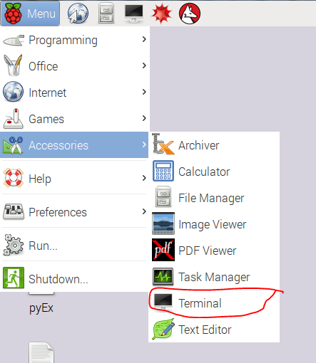
and you get pi desktop like this(I used the raspbean Jesse Disc Image)
Go to the Menu --> Accesories --> Terminal
Type the following Command
sudo ifconfig
and you get
Under eth0 you get the Following
inet addr : XXX.XXX. X . X Ip address of your PI
Bcast
and Mask
note Down those values
and then type following in command window
netstat -nr
you get
Note down the gateway Value
By default the Dynamic IP addressing is Set. So we need to change it into the Static
So go to the Terminal And type
sudo nano /etc/network/interfaces
replace line iface etho inet manual
with
change the Values as shown above and cross check them with noted values
and hit control-X and save it then Reboot it using
sudo reboot
once again check the ifconfig
if the IP Address is Not changes
go to the terminal and type
sudo nano /etc/network/interfaces
and insert following
then reboot again.. you shoud get static ip..
for Remote Monitor
goto the terminal and type the following
sudo apt-get install xrdp
and install the xrdp package.
and reboot your pi.
then Go to your Windows PC/Laptop.
open Command prompt and enter mstsc
or On Search enter Remote Desktop Desktop Connection
you get
and enter your IP in computer
hit connect
Enter your Username and Password.
and You Get the Pi desktop like this.
If you are facing any problem in this Procedure Leave a Comment or
Connecting Two Push Buttons To Arduino.. Taking the Input From Them Using DigitalRead() via Arduino Digital Pins and Switching On the Led If The Both the Push Buttons are Pressed.