The key function of an diode is to control the direction of current-flow. Current passing through a diode can only go in one direction, called the forward direction. Current trying to flow the reverse direction is blocked. They’re like the one-way valve of electronics.
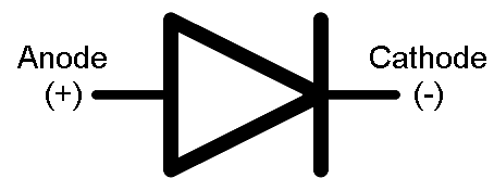
The terminal entering the flat edge of the triangle represents the anode. Current flows in the direction that the triangle/arrow is pointing, but it can’t go the other way.
Forward Voltage
The terminal entering the flat edge of the triangle represents the anode. Current flows in the direction that the triangle/arrow is pointing, but it can’t go the other way.
Forward Voltage
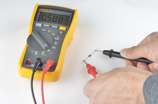
In order to “turn on” and conduct current in the forward direction, a diode requires a certain amount of positive voltage to be applied across it. The typical voltage required to turn the diode on is called the forward voltage (VF). It might also be called either the cut-in voltage or on-voltage.
it is Typically 0.5 volts for Silicon Diode.
BreakDown Voltage :
Breakdown Voltage
If a large enough negative voltage is applied to the diode, it will give in and allow current to flow in the reverse direction. This large negative voltage is called the breakdown voltage. Some diodes are actually designed to operate in the breakdown region, but for most normal diodes it’s not very healthy for them to be subjected to large negative voltages.
Working With LED's :
LED - Light Emitting Diode
The LED does have and "equivalent" resistance, but it's value is wholly dependent on the value of the current flowing through the LED and dynamically changes with it.
To deal with an LED you start with the forward current that you need, typically about half it's maximum rated value (lets use 20 mA).
Next you estimate what the forward voltage drop will be with that current flowing through the LED. If you have a datasheet for the LED you may be able to get a fairly accurate value, otherwise you take a guess based upon your experience or the experience of others (I usually use 1.7v for a red LED).
Next you pick out a supply voltage which must be higher than the voltage you just determined (I'll use 5v).
Now you can use Ohm's law to determine the required resistance. The voltage across the resistor will be the difference between the supply voltage you decided to use and the voltage that you guessed would be across the LED (5v - 1.7v = 3.3v). The current through the resistor will be the same as the current through the LED (20mA). Ohm's law for the resistor says that R = V/I (R = 3.3/0.020 = 165 ohms).
You then pick the closest value resistor that you happen to have and stick that in your circuit. Most likely the current won't be exactly what you desired and the LED voltage won't be what you guessed would be there but you won't see any smoke either and you will see light from the LED.
Check the Data Sheet of Sample LED here.
And see the Maximum Values
