Tuesday, 23 December 2014

Driving high current devices Using Arduino

The maximum current capacity of Arduino digital pin is 20 mA, what if we wanted to power the devices or control the devices using Arduino which consume the current more than 20 mA?
The Basic Alternative is using Transistor to provide a Power supply to the high current/voltage devices.
A transistor will allow you to switch the Motor On and Off safely, as well as to control speed using Pulse Width Modulation techniques
NPN Transistor as a voltage controlled Switch.
NPN transisitor

Current flows through collector and out of emitter.
By controlling the voltage at the base pin we can control the flow if current in the transistor
The circuit to control the motor using arduino is

circuit

When sufficient voltage is applied at the base pin i.e arduino pin Digital High the flow of current is allowed through transistor.
When no voltage is applied at the base the transistor is act like a open switch. There is no current flow between emitter and collector.
In the above circuit the transistor is essentially connecting and disconnecting one terminal of Motor from ground and determining when a complete circuit is made with battery.
We must connect both power supply grounds together to ensure common reference point between voltage levels in two parts of the circuit.

Thursday, 11 December 2014

Arduino ICSP Pins And Boot loader

We can program arduino With USB Cable.. That's nice and super easy way...
Do U Ever wonder How the Arduino Chip [atmel ATmega 328P] is programmed in factory to do all this magical stuff. I got the same doubt and started to digging the Net for it..
In process I came Across ICSP

ICSP is Acronym for In Circuit Serial Programming

As The Name Indicates We can Program Micro controller when the Circuit assembly is completed(In circuit)

from Wikipedia


In Circuit Serial Programming (ICSP) is a method directly programming AvR's and PIC controllers
ICSP is a way that allows us to program the chips when they are in circuits


In arduino It helps in arduino chip Directly with AVR Instructions Without need to arduino IDE. In general Avr Micro controller are programmed with an ICSP, which talks to the micro controller via Serial Peripheral Interface (SPI... Which is an another Long topic we can talk about this in another Post)


In General, ATMega microcontrollers are written in C or assembly Language and programmed via the ICSP interface using another Hardware to upload the Code

So what makes us possible In arduino to upload the code by simply plugging USB cable to our arduino?

that credit goes to the small chunk of program taking a 2k memory in our ATMega Chip which is loaded in factory Named boot loader
Boot Loader allows a Serial USART (Universal Synchronous/ Asynchronous Receiver/Transmitter) to load the arduino Program to the Arduino Without using a separate programmer

In Arduino Uno a secondary Micro controller serves as an interface between a USB cable and serial USART pins on Main Controller[ATMega 368p]
Nick gammon write everything in a one post about Arduino UNO PINOUT checkout here

Boot Loader is basically a HEX file that runs when you power on or reset the board
It is very similar to BIOS that runs on your PC


BIOS : [Basic Input / Ouput System] the bios software is built in PC and it is first software run by PC when you power ON.
the fundamental purpose of BIOS is to Initialize and test the system hardware components and to load the OS from a mass memory device


The BOOT LOADER does two things :
first, it looks around to see if computer is trying to program it. If it is, then It grabs the program From PC and upload it into IC's Memory in specific location so it is not overwrite the boot loader

secondly if computer isn't trying to upload the code, it tells the chip to run the code that's already stored in memory.

Once it locates and runs the program the arduino loops through the program and does as long as board power has power.

after reading all this you may get this small doubt:
Ok.. Boot loader is a chunk of code that runs initially when board power On or Reset to check whether computer is trying to upload the code... But we are not restart / reset the arduino each and every time we try to upload the code...
so how's arduino is doing this
the answer is when you try to upload the code you need to send the UPLOAD command from Arduino IDE, The command instructs USB to Serial chip to reset the Main MCU, hence forcing it into boot loader, then computer immediately begins to send the program contents, which MCU is ready to Receive it Over UART connection.

Serial Monitor with Data logging....

Arduino IDE has an Built-in Serial Monitor. It is a good way to print the some data and debug the program.

what if we wanted to save the monitoring data.. like log the temperature of room in a 12 hours or something like that..?

Serial Monitor come with Arduino IDE doesn't have a data logging capabilities.. so we need an alternative to that..

we can program in python or matlab to save the data... But as a Newbie i only know Arduino Language. I didn't know even know the C or C++ more than Arduino Language.

So I need a much simpler one with out any further coding...

the program I am using with arduino for simple data logging is putty.
it is sufficient enough for simple data logging
you can download it from here
download the exe file and install it.
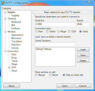
after installing when you open it it look like


change the connection type to Serial and specify the serial line(com) and speed(baud rate) for com 10 and 9600 baud rate the setting will look like this


click on the Logging and change the following settings as shown in images below


we can change the serial line settings in the Serial category as shown in fig.

then load the following code into the arduino.. using arduino IDE

void setup() {
Serial.begin(9600);
Serial.println("Anil");
}

void loop() {
Serial.println("Kunchala");
delay(1000);

software_reset();
}
void software_reset(){
Serial.println("Do you want to print again?");
Serial.println("enter y or n");
while(!Serial.available()){
}
char in_char = Serial.read();
if (in_char == 'y'){
//if receivd character is y then Reset the arduino
asm volatile("jmp 0");
}
else{
//else call the function to repeat the same procedure
software_reset();
}
}


this code is from my previous post.. you Can Find it in Here

then Close IDE and Open PUTTY configure the above settings and click OPEN

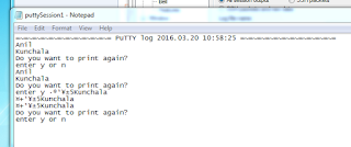
and the log is saved in my desktop file named Putty like this..

Wednesday, 10 December 2014

Pull up and Pull Down Resisitors

All Arduino Pins are Inputs by Default. lets say you wanted to use pin 3 as input to the push button and the circuit will look like this
Push Button Config

if we wanted to send the logic 0 to do specific work we press the push button and it connects the digital pin3 of arduino to the ground.
what is the state of the pin3 when we dnt wanted to send the logic 0 to the circuit?
it connects to the nothing..

"If nothing is connected to the pin and your program reads the state of pin, will it be high or low?? it is difficult to tell" this phenomena is referred to as
floating.

"just because nothing is connected to the input pin doesn't mean it is a logical zero" even it is we dont want to send the logic 0 in present condition when
button is not pushed ,i.e when nothing is connected to the pin.

In this situation Pull up/down resistors are come in handy.

in the above circuit when the button is not pressed the default condition of the circuit has to be logic high(1). so if we connect the vcc to the circuit like this

Pull Up with out resistor

it will full fill our condition to make default position as logic high when button is not pressed.
But When the button is pressed the button it connects the Vcc to Ground, which is called as short, and we have to avoid short circuits. so we need to connect the
resistor between the Vcc and Ground.
Pull Up with resistor

when the button is pressed it connects the input pin directly to the ground, the current flows through the resistor to the ground.


the same scenario is work for Pull Down resistor in this case the default state is low. again the resistor in the circuit is used to avoid the short betweeen vcc and GND
Pull Down Resistor


we can find more information here and here

when to use pull up/down here

Tuesday, 2 December 2014

Resetting Arduino

I ran into situation where I need to reset(?) arduino.. Where adrduino need run the setup() function, to load the new variables to execute the same code.
the initial code is like this.

void setup(){
load some variables
}
void loop(){
run the code according to the varibles
}


I don't want to RESET arduino everytime. so I dig the net to reset the arduino.

I gone through this links

In the link he described it as Dirty Solution
even though i think it meeds my needs. it executes the code from starting point


moves the control to the beginning of the program using an assembly statement jump.


so i write this code to understand myself

void setup() {
Serial.begin(9600);
Serial.println("Anil");
}

void loop() {
Serial.println("Kunchala");
delay(1000);

software_reset();
}
void software_reset(){
Serial.println("Do you want to print again?");
Serial.println("enter y or n");
while(!Serial.available()){
}
char in_char = Serial.read();
if (in_char == 'y'){
//if receivd character is y then Reset the arduino
asm volatile("jmp 0");
}
else{
//else call the function to repeat the same procedure
software_reset();
}
}

the result will look like this..
Capture


Ok... I got what I need But..
What is the meaning of the line
asm volatile("jmp 0");

as previously said it restarts the arduino from starting...,(memory location 0x00)
we can have the answer...

asm volatile is typically used for embedding assembly snippets inside C routines


so it is assembly instruction.

what is the meaning of jmp instruction

The JMP instruction provides a label name where the flow of control is transferred immediately. The syntax of the JMP instruction is:

JMP label


from WIKIPEDIA


the JMP instruction performs an unconditional jump. Such an instruction transfers the flow of execution by changing the instruction pointer register.


this line transfers the execution control to the starting memory location and has nothing to do with any other arduino registers. so registers does not go to default state(INPUT) what actual RESET (by pressing the RESET button).

Monday, 1 December 2014

Declaring the variable as Static

When I digging the net to learn some Serial monitor Basics, I gone through this post
it is really helpful though.

So I think I can Start some.. I started to write it down on arduino IDE to execute it.
So first I literaaly copied it into IDE and executed it and get the OUTPUT as expected..
I think Whoh... I learned everything about Serial communication and i started to code in my own words..

and it ended up something like this..

#define DATABUFFERSIZE 80
char dataBuffer[DATABUFFERSIZE+1]; //Add 1 for NULL terminator
byte dataBufferIndex = 0;
String question_1 = "Enter a value";
void setup(){
Serial.begin(9600);
ask_question(question_1);
while(!getSerialString()){
//wait here
}
int a = atoi(dataBuffer);
Serial.println("the value of A is::");
Serial.println(dataBuffer);

}
void loop(){

}

void ask_question(String question){
Serial.println(question);
}

boolean getSerialString(){
byte dataBufferIndex = 0;
while(Serial.available()){
char incomingbyte = Serial.read();

if(incomingbyte=='\r'){
dataBuffer[dataBufferIndex] = 0; //null terminate the C string
//Our data string is complete. return true
return true;
}
else{
dataBuffer[dataBufferIndex] = incomingbyte;
dataBufferIndex++;
}

}

return false;
}

in the line byte dataBufferIndex
I dont understand the Variable declaration static
so i removed it and still didn't get any error so i think it will execute , and tried to execute it...
and get Output something like this
[caption id="attachment_48" align="alignnone" width="214"]with out static variable in post with out static variable in post[/caption]

as unexpected... the result didn't come it just printing the empty line...

and i didn't know what went wrong.. So I compare the code line to line to find out what went wrong....
the change is i didn't declare it as Static.

I didn't want to use the variable as Static... Why?
because i didnt know what it is.

So I googled about Static and find this in arduino site
Static

The static keyword is used to create variables that are visible to only one function. However unlike local variables that get created and destroyed every time a function is called, static variables persist beyond the function call, preserving their data between function calls.
Variables declared as static will only be created and initialized the first time a function is called.


and unsurprisingly.. I didn't understand a bit in it.
SO i gone to the arduino forum and posted it and got my reply like this:

You are still always resetting dataBufferIndex to 0... I hate repeating myself but.. you have to reset it only after you have received the '\r'.

so i thought byte dataBufferIndex = 0; this line is the wrong line But in the JHaskell's blog he declared it.
as the forum suggests i declared the variable as a global variable.
Quick note: Variables declared Above the setup() function is all global variables
and the code will look like

#define DATABUFFERSIZE 80
char dataBuffer[DATABUFFERSIZE+1]; //Add 1 for NULL terminator
byte dataBufferIndex = 0;
String question_1 = "Enter a value";
void setup(){
Serial.begin(9600);
ask_question(question_1);
while(!getSerialString()){
//wait here
}
int a = atoi(dataBuffer);
Serial.println("the value of A is::");
Serial.println(dataBuffer);


}
void loop(){

}

void ask_question(String question){
Serial.println(question);
}

boolean getSerialString(){
while(Serial.available()>0){
char incomingbyte = Serial.read();

if(incomingbyte=='\r'){
dataBuffer[dataBufferIndex] = 0; //null terminate the C string
//Our data string is complete. return true
return true;
}
else{
dataBuffer[dataBufferIndex] = incomingbyte;
dataBufferIndex++;
}

}


return false;
}

code displays the entered value.. and End of Story.
and Today I accedently look into the STATIC variable i thought i understand something about it

so go back to our first code with variable declaration in getSerialString() function
this function will check whether the '\r' Carriage Return is received or not and return true if the '\r' is received.

Arduino will executed 100's of instruction within time of receiving One character so it will call function the many times while receiving the character and gap between receiving the character.
so the variable dataBufferIndex will initialized to 0 every time it is called. so for every character it will called 100's of times. so we get reply for the function getSerialString() when we received only '\r' character. so when we received '\r' we write the NULL in the dataBuffer in the position of dataBufferIndex which is 0 i.e we are saving a null character in the dataBuffer so program is printing the NULL character itself which is a empty string

So we need a declaration of variable which as to be declared Once and does not reinitialize its value every time it is called and. and according to our program it has to reinitialize when it received '\r' character.

if we look at the explanation of static keyword again:
Static

The static keyword is used to create variables that are visible to only one function. However unlike local variables that get created and destroyed every time a function is called, static variables persist beyond the function call, preserving their data between function calls.
Variables declared as static will only be created and initialized the first time a function is called.

so this is exactly what we need.. So if I change the code using the static variable the code will be

#define DATABUFFERSIZE 80
char dataBuffer[DATABUFFERSIZE+1]; //Add 1 for NULL terminator
byte dataBufferIndex = 0;
String question_1 = "Enter a value";
void setup(){
Serial.begin(9600);
ask_question(question_1);
while(!getSerialString()){
//wait here
}
int a = atoi(dataBuffer);
Serial.println("the value of A is::");
Serial.println(dataBuffer);


}
void loop(){

}

void ask_question(String question){
Serial.println(question);
}

boolean getSerialString(){
static byte dataBufferIndex = 0;
while(Serial.available()>0){
char incomingbyte = Serial.read();

if(incomingbyte=='\r'){
dataBuffer[dataBufferIndex] = 0; //null terminate the C string
//Our data string is complete. return true
return true;
}
else{
dataBuffer[dataBufferIndex] = incomingbyte;
dataBufferIndex++;
}

}


return false;
}


which gives the exact result as second code without global variable...